VLAN Challenge (last edited 2020-02-06)
Overview
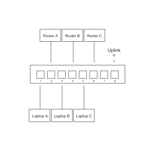
The objective of this assignment is to determine a VLAN strategy and port configuration that overlays the given routing topology onto a managed 8-port switch.
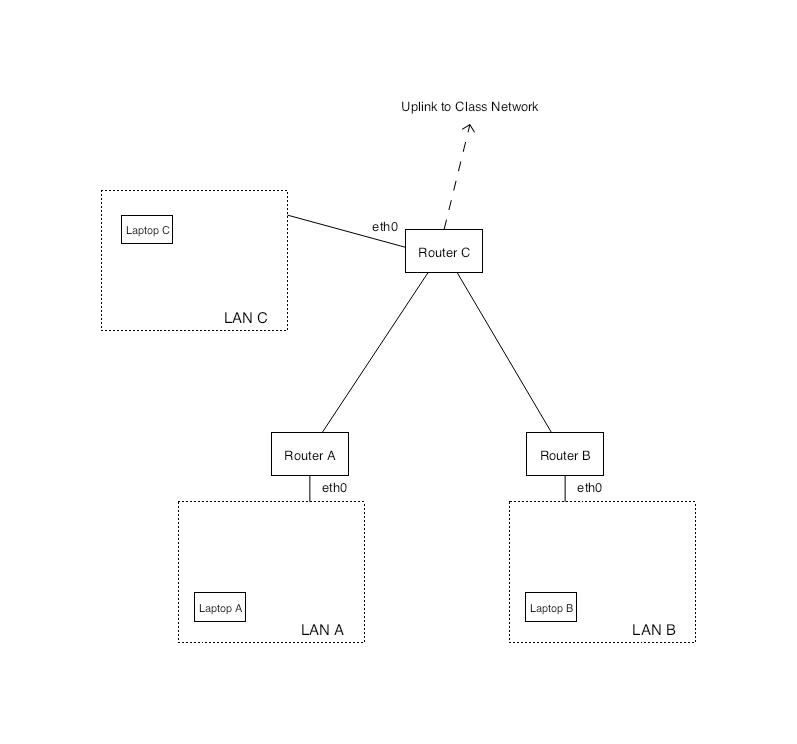
The routing topology that you will be working with in this challenge is representative of the topology used in our final, group project. In this topology, we have three autonomous systems, i.e., networks that are managed independently from one another. Each of our three routers serves a group of local users via a LAN segment in addition to being connected to external networks via point-to-point routing links.
The network positioned at the top of the diagram will function as an Internet Service Provider (ISP) for the other networks networks, routing traffic between them and other groups within the class. The links between routers are known as routing links. Each one represents a separate point-to-point network over which the routers will forward messages and share information about the inter-network topology.
Instructions
Identify broadcast domains
Identify the distinct broadcast domains in the system and assign a different VLAN label (between 2 and 4094) to each of these network segments.
Define physical connections
Assign each physical connection to a port on the switch. Since the topology is determined by port configuration, you will need to keep track of which device and network interface is associated with each port. Choose an order that is easy to remember.
Create port configurations
Once you have identified the VLANs and mapped ports to physical topology, you can begin to define the port configurations. For each port, you will define a native VLAN (untagged) and zero or more tagged VLANs. A port can have both types of VLANs associated with it, though there can only be one native VLAN configured for any port.
Untagged ethernet frames received on a port will be mapped internally to the native VLAN of the port and can only be forwarded (or flooded) through links attached to ports that are configured with the same VLAN (tagged or untagged). When a VLAN is configured to be tagged on a specific port, that port will add a VLAN identifier to outgoing frames and read/remove the identifiers from incoming frames.
Adding a tagged VLAN to a port creates a trunk. Trunk links expect the same tag configuration on both ends of the link, i.e., they require explicit configuration on both sides of the trunk. Ports without any tagged VLANs are called access ports. These are preferred for most applications since the VLAN configuration will be encapsulated within the switch and transparent to users.
LAN connections
For simplicity, start the process by defining the port configurations for a single broadcast domain associated with one of the LANs in the topology, e.g., LAN A. Pay close attention to the requirements given in the next section, which state that LAN connections to A, B, and C should be accessible without tagging.
Routing links
Once you have completed the configuration for independent LANs, turn your attention to the routing links between the LANs. Update the configuration for each side of the routing link (two physical ports) with the appropriate VLAN configurations.
Uplink
Finally, turn your attention to the connection that forms the uplink to the core network for the class. The uplink is a routing link, and it is configured in much the same manner as the other routing links in our topology. However, pay close attention to the assignment specifications and the implications for the final port configuration.
Specifications
In addition to the following the given network layer topology, please align your VLAN strategy with requirements below:
Layer-3 Network Diagram
Example Physical Diagram
Access links to general LANs
LANs A, B, and C are general purpose networks and should be exposed as untagged VLANs. This enables us to alternate seamlessly between a direct connect from our laptop to Pi and a connection that runs through the switch. If we were to rely on tagged VLANs to access a given LAN, you would need to configure VLANs on your laptop in order to connect directly to the Pi.
Tagged Routing Links
Routing links may rely on tagged VLANs. The router will connect to these VLANs via virtual network interfaces that are configured to exchange tagged Ethernet traffic rather than standard, untagged frames. The router side of this configuration is beyond the scope of this exercise.
Untagged Uplink Connection
The remote end of the uplink connection will be untagged. Make sure that you configure the associated port accordingly.
Eliminate Extraneous Connections
For each port, only expose the VLANs that are necessary to satisfy the routing requirements indicated in the diagram. Adding additional VLANs creates unintended paths for communication, e.g., allowing Laptop A to communicate directly with Laptop B. For the purposes of this assignment, treat this sort of unintended pathway as a security exposure.